
Telecommunications infrastructure rarely follows a uniform route. Fiber cables may pass through narrow urban trenches, cross open areas on aerial spans, or share limited underground corridors with existing utilities. Standard circular ducts cannot address every installation constraint, so network planners increasingly need profiles shaped around the physical demands of specific routes.
Custom extruded plastic duct development requires balancing space efficiency, cable protection, installation methods, and manufacturing feasibility. Each cross-sectional feature should serve a defined purpose rather than merely creating an unusual shape.
Oval Ducts for Space-Constrained Underground Routes
Narrow trenches can restrict the dimensions of ducts installed alongside water pipes, electrical conduits, and other buried services. An oval profile may provide a useful alternative to a circular duct when trench width is limited but sufficient internal space must remain for cable installation. Its suitability depends on the available height and width, the required cable capacity, and the mechanical loads expected after backfilling. A flatter shape is not automatically more efficient if deformation reduces the usable internal area.
Engineers must assess how an oval duct responds to external pressure and installation conditions. Soil loads, compaction equipment, surrounding materials, and localized contact with adjacent infrastructure can all influence deformation. Wall thickness and polymer stiffness affect resistance to crushing, while the relationship between the duct’s axes determines how its shape changes under load. Testing should reflect the intended burial depth and installation environment rather than rely solely on nominal dimensions.
Cable installation also requires attention to the internal surface and route geometry. Excessive curvature, roughness, or local deformation can increase pulling resistance and complicate future cable replacement. Designers should consider cable diameter, bend radius, pulling distance, and access-point spacing before fixing the duct profile. These parameters help determine whether an oval cross-section provides a practical benefit over conventional round tubing.
Figure-8 Profiles for Aerial Fiber Installation
Aerial telecommunications routes introduce different structural demands from buried installations. A figure-8 duct typically combines a cable duct with an integrated messenger section, allowing the supporting element and protective conduit to form one continuous profile. This arrangement can simplify installation compared with systems that require a separate support wire, but the design must account for span length, cable weight, wind loading, temperature variation, and the forces transferred to poles or attachment points.
The geometry of the messenger section is especially important because the supporting portion must carry tensile loads without compromising the cable enclosure. Engineers need to evaluate material strength, stress concentration around the connecting web, and the possibility of deformation during installation. The duct portion must retain enough internal clearance to protect the fiber cable, while the connecting section must tolerate the expected loads and environmental exposure. Performance depends on the entire profile, not just the strength of its supporting element.
Material selection and validation should reflect the intended service environment. Ultraviolet exposure, temperature cycling, moisture, and long-term mechanical loading may influence polymer performance over years of outdoor use. Testing can include tensile assessment of the messenger section, dimensional checks, environmental conditioning, and evaluation of the connection between the two portions. Installation instructions should also specify acceptable handling methods and attachment practices to reduce damage during deployment.
Multi-Bore Bundles for Compact Urban Networks
Urban network expansion often requires several small ducts within a confined corridor. Multi-bore profiles combine multiple internal channels into a single extruded bundle, helping organize individual microducts and simplifying route identification. Each bore can serve a separate cable or future network expansion, depending on the system design. The arrangement may reduce the need to manage numerous independent ducts, although its usefulness depends on cable capacity, installation access, and the amount of space available along the route.
Internal channel geometry affects how easily cables can be installed and replaced. Bore diameter, wall consistency, surface condition, and curvature along the route influence friction and pulling performance. Designers must also consider how unused channels will be sealed against water and debris, how individual routes will be identified, and whether the bundle can accommodate planned network growth. A high channel count offers little practical value if the internal dimensions or installation conditions restrict cable placement.
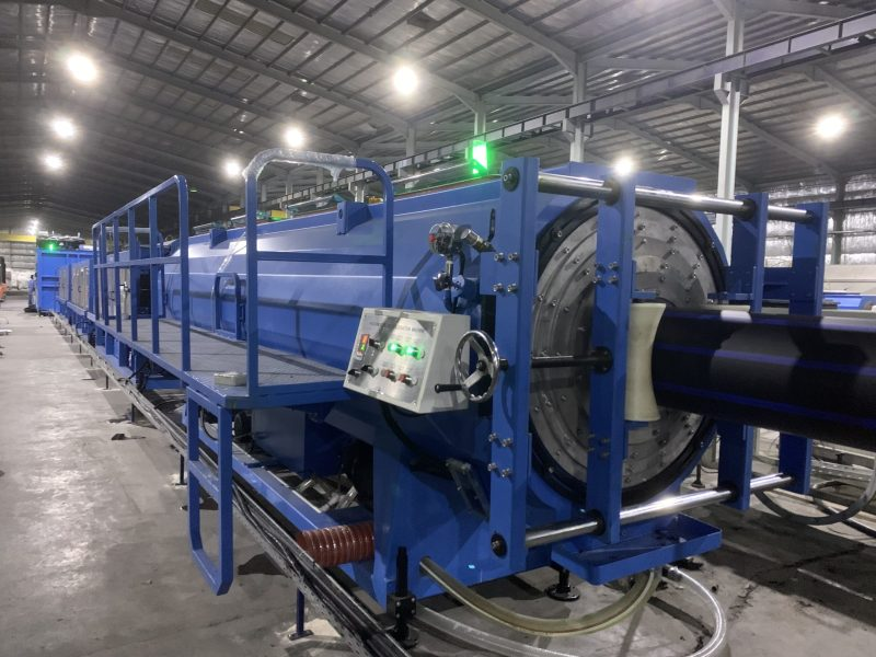
Manufacturing a multi-bore profile presents its own process-control challenges. The die must distribute polymer consistently around each channel while preserving the separating walls and overall bundle dimensions. Uneven flow or cooling can shift internal bores, change wall thickness, or cause distortion during haul-off. A suitable extrusion pipe machine should provide the necessary control over melt flow, die configuration, cooling, and dimensional stability. Suppliers such as DEKUMA, which has a history of supplying extrusion lines for pipe manufacturers, can be assessed for relevant engineering experience, but the specific profile and its production requirements must determine equipment suitability.
Conclusion
Specialist telecom duct profiles are most useful when their geometry responds directly to installation constraints. Oval ducts can address restricted trench dimensions, figure-8 designs integrate aerial support with cable protection, and multi-bore bundles organize several routes within a compact footprint. Each option introduces distinct considerations involving structural loads, cable access, material behavior, and dimensional control.
Before approving custom extruded plastic designs, network operators and manufacturers should define the installation conditions, identify measurable acceptance criteria, and validate performance through appropriate testing. An extrusion pipe machine must then be matched to the profile’s geometry and polymer requirements. DEKUMA can be evaluated alongside other suppliers on verified technical capability and project-specific support. The strongest design is the one that solves a real deployment problem while remaining practical to manufacture, install, and maintain.